Smart door
A card-access door controller on an STM32 Nucleo, built with a small team for UNSW's DESN2000
DESN2000
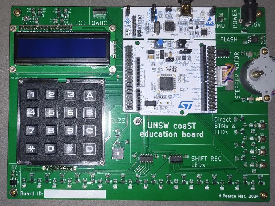
This project was my first real exposure to microcontrollers. In a team of three (later two, for part of the term), we were tasked with building a card-access door controller on an STM32 Nucleo for DESN2000. We were given a lot of freedom regarding features and implementation, as long as the system was intuitive and safe to use. We ended up implementing various functions including sector-based encryption, a custom theme engine and an LDR-based alarm system, all of which worked very well in the final demo.
How it works
One light sensor (LDR) is placed on either side of the door. If motion is detected through a shadow, the door asks for a card on the NFC reader. To be accepted, the card's UID has to be on a list stored in the MCU's flash, and the card has to carry a secret that we wrote to one of its sectors. Coming from the inside, no card is needed and the door simply opens.
The door itself swings 90° on a stepper motor, inward for entry and outward for exit. Since safety was one of the main requirements, the door won't start moving until the side it swings into is clear, pauses mid-swing if someone steps into its path, and re-opens if a sensor is triggered while it's closing.
For security, we added a tailgating check: on an entry, exactly one person is allowed to pass the inside sensor, so a second break triggers an alarm. Five rejected cards in a row also trigger an alarm. To override, an admin fob can clear alarms, enrol new cards and unlock a keypad menu on the LCD, with scheduled unlock windows, a clock, themes and card management. We also added two custom themes (Star Wars and James Bond) for the buzzer and the LED signals.
be the person at the door
0°
Waiting for someone to walk up.
try: stand outside → valid card → step away → stand inside (walk through) → step away. Then do it again but walk through twice.
A browser re-implementation of the passage state machine (the real firmware has 10 states; scheduled unlock is left out here). Timings are sped up.
How the firmware is laid out
The firmware we wrote is a bare-metal cooperative superloop without an RTOS. Every module has an init() and a non-blocking task() function that gets called once per loop, and all timing is based on millisecond deltas rather than blocking delays. The most important rule for the team was that only `hal_wrapper.c` is allowed to touch hardware. This meant everyone could write code against stubbed functions before the hardware was even wired up, and when a pin had to move, only one file needed to change.
Some of the modules worth mentioning:
- LDRs: each sensor uses hysteresis (separate thresholds for covered and clear) plus debouncing, and produces a one-shot event when it becomes covered.
- Card storage: authorised cards are kept in a small log-structured database in the last 2 KB page of flash. Since flash can only clear bits, adding a card appends a new entry and removing one zeroes its status word. The status is written last, so a power cut halfway through a write leaves an empty slot instead of a corrupted one.
- NFC driver: the PN532 frames are built by hand, and the driver refuses to write to sector 0 or any sector trailer, so a bug can't accidentally lock a card's keys.
- LCD: the display needs microsecond delays that
HAL_Delaycan't provide, so they're generated using the Cortex-M's DWT cycle counter.
case SYS_OPEN: {
    /* Tailgate invariant: count inside-sensor breaks against the
     * allowance for this direction. */
    if (ldr_became_covered(LDR_2)) {
        s_inside_breaks++;

        if (s_inside_breaks > s_inside_allowance) {
            sys_set_tailgate_flag(true);
            enter_alarm();
            break;
        }
    }
    (void)ldr_became_covered(LDR_1);       /* consume; not part of the rule */

    /* Close once the window has elapsed AND the doorway is empty. If it is
     * still occupied, keep waiting and never close on a person. */
    if ((now - s_open_since_ms) >= OPEN_WINDOW_MS && ldr_all_clear()) {
        if (motor_close()) {
            sys_set_state(SYS_CLOSING);
            s_state_started_ms = now;
        } else {
            enter_system_error();
        }
    }
    break;
}
The tailgate check: an entry allows one break of the inside sensor, an exit allows none.
Integration & Debugging
Most of the difficult bugs only appeared once all the modules were running together on the real hardware:
- An alarm that never cleared. Since tailgating is detected while the door is open, resetting the alarm with the door still open immediately re-triggered it. The fix was to close the door first and only clear the alarm once it's shut.
- Ghost overrides. Tapping the admin fob during a door cycle latched a request that re-opened the door as soon as it had closed. Overrides are now discarded while the door is moving.
- False motor timeouts. If the door paused for a person in its path, it would trip the 10 s motor timeout. Pausing now suspends the timeout, and resuming restarts it.
- Competing LCD messages. Several modules wanted the display at the same time, so we split messages into critical ones (alarms and faults, which are always shown) and routine ones (door progress, which gives way to an open admin menu).
What I learned
Since this was my first real microcontroller project, I learned a lot just implementing the basics. The labs taught us to control the individual peripherals including a shift-register LED bar with debounced buttons, a 4×4 keypad and LCD calculator, UART with a 1 ms timer tick, and a PWM buzzer. Most of these ended up in the final door in some form.
Over the course of the project, I got hands-on experience with most of the common peripherals on the STM32:
- I2C: the PN532 card reader sits on I2C1 at address 0x24. Since we wrote the frame protocol by hand instead of using a library, I had to properly understand addressing, acknowledgements and how to poll a slow device until it's ready.
- ADCs and analogue pins: the two LDRs are read through ADC2 and ADC3 at 12 bits. Light levels change throughout the day, which is why the hysteresis and debouncing ended up being necessary.
- Timers and PWM: the buzzer runs on a timer channel prescaled to 1 MHz, so the auto-reload value directly sets the pitch, which is how the themes play their tunes.
- UART: both sides have to agree on the baud rate and frame format, otherwise the terminal only shows garbage.
- GPIO and timing: scanning the keypad matrix row by row, stepping the motor coils in sequence and driving the LCD with microsecond delays.
Beyond the individual peripherals, the biggest takeaway was how much of embedded work comes down to reading datasheets and reference manuals, and how a non-blocking main loop keeps everything responsive even with many things going on at once.